Servo ID Configuration Method for Serial Bus Servo Controller
1. Introduction
This tutorial features the Hiwonder LX-824HV servo as an example and applies to all models of Hiwonder serial bus servos. Configuring the servo ID requires the use of a serial bus servo controller and the Bus Servo Control software.
2. Configuration Instruction
2.1 Preparation
2.1.1 Hardware Requirements
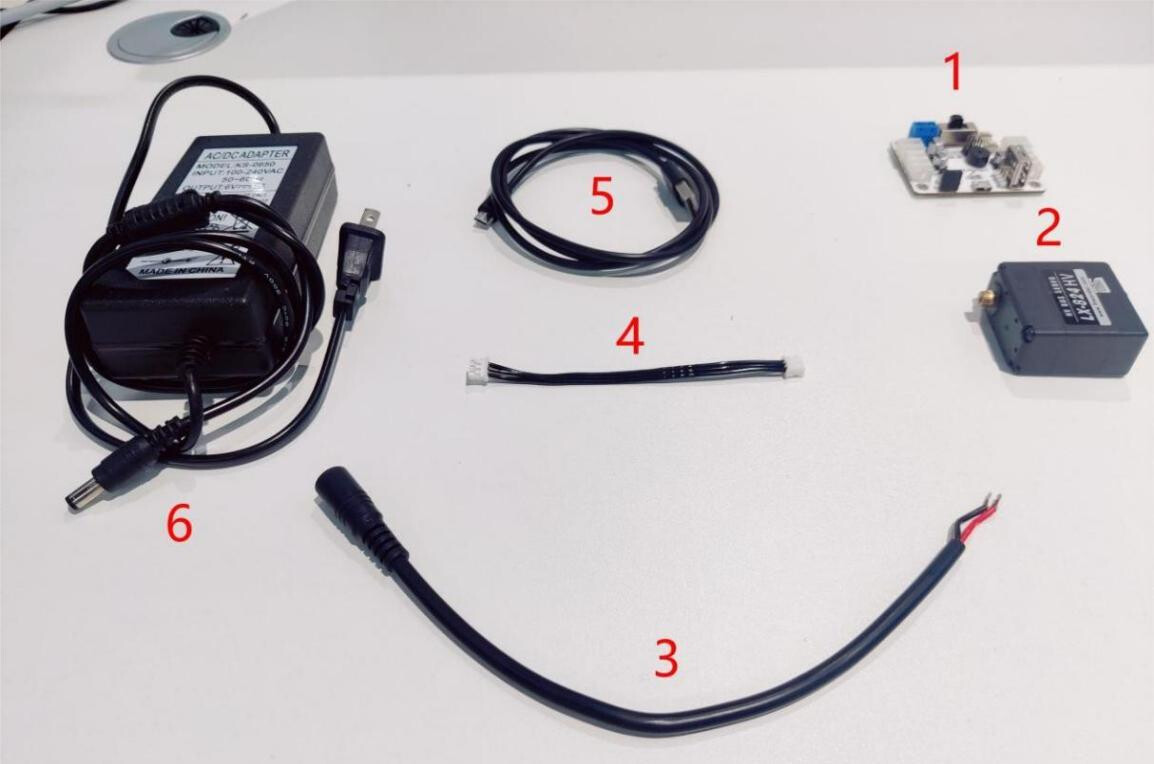
The required hardware components must be prepared in advance, as shown in the figure below.
| No. | Name |
|---|---|
| 1 | Serial bus servo controller |
| 2 | Serial bus servo |
| 3 | Power adapter cable |
| 4 | 3-pin servo cable |
| 5 | Hiwonder 6 V to 8 V power supply or battery |
| 6 | Micro USB data cable |
2.1.2 Hardware Connection
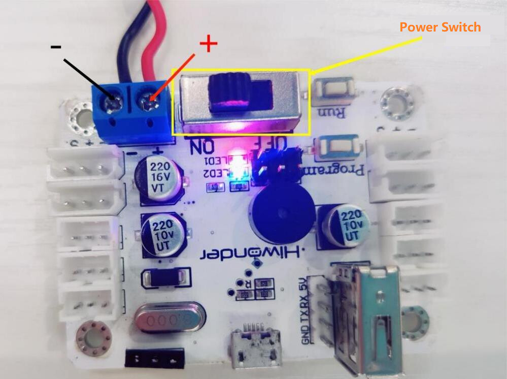
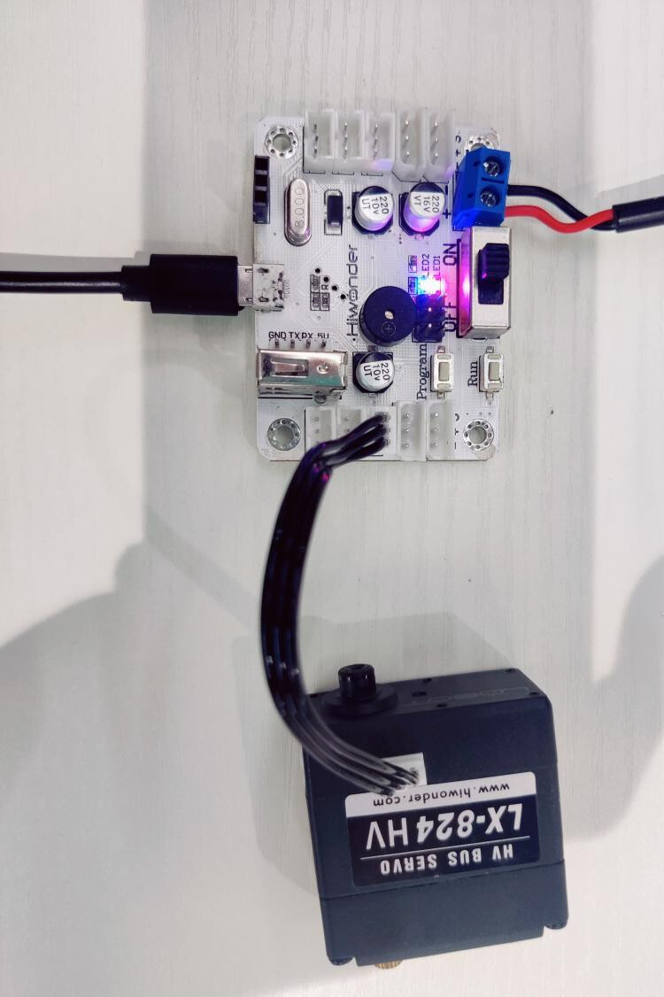
- Connect the power supply: Connect the power adapter cable where the red wire connects to the positive and the black wire connects to the negative, as shown in the figure below. Secure the connections with a screwdriver after wiring and flip the power switch to ON. The blue LED and red LED on the controller will light up to indicate a successful power-on status.
Reverse connection is strictly prohibited. Always use a power supply or battery that matches the specified servo drive voltage.
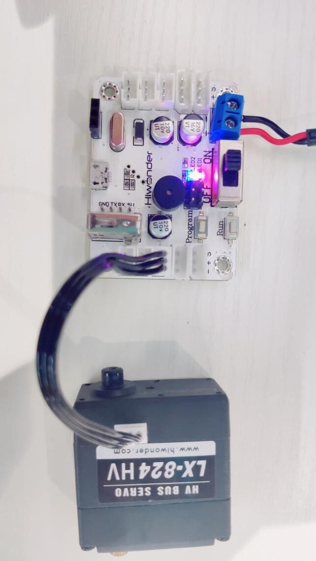
- Connect the servo and the controller: Connect the serial bus servo to the controller using the 3-pin servo connection cable, as shown in the figure below.
The ports on the servo and the controller are interchangeable, and any two available ports can be selected for connection.
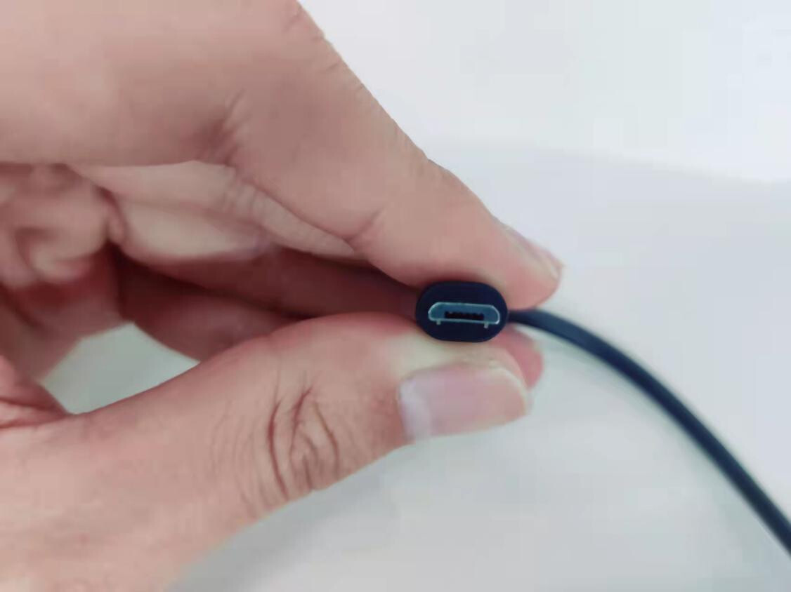
- Connect the serial bus servo controller to the computer: Use the Micro USB data cable shown in the first figure below to link the serial bus servo controller to the computer, as illustrated in the second figure below.
2.1.3 Software Setup
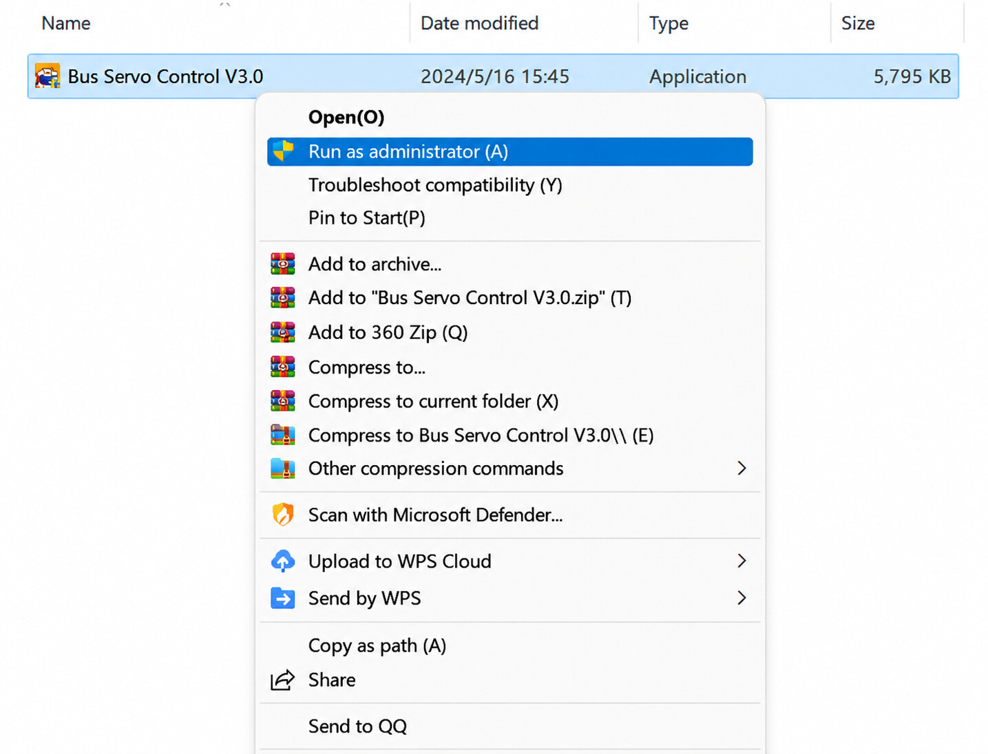
Software Installation: Open the installation package with administrator privileges to ensure a successful installation of the Bus Servo Control software, as shown in the figure below.
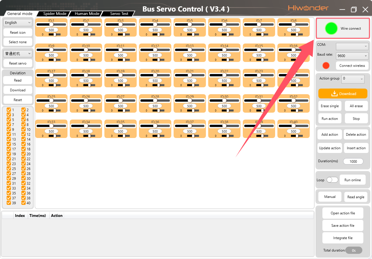
- Connect to the host computer: Launch the Bus Servo Control software, and a connection with the servo controller will be established automatically without extra operations. Upon a successful connection, the indicator light in the upper right corner of the Bus Servo Control software will turn green and display a wire connect status message as shown in the figure below. If the connection fails, the indicator will turn red and display a disconnected status message, which requires checking the data cable connection to the computer.
2.2 Servo ID Configuration
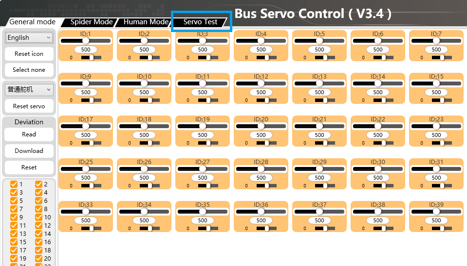
Click the Servo Test button to access the servo configuration interface shown in the figure below.
Only one servo can be debugged at a time because connecting multiple servos simultaneously will cause address conflicts.
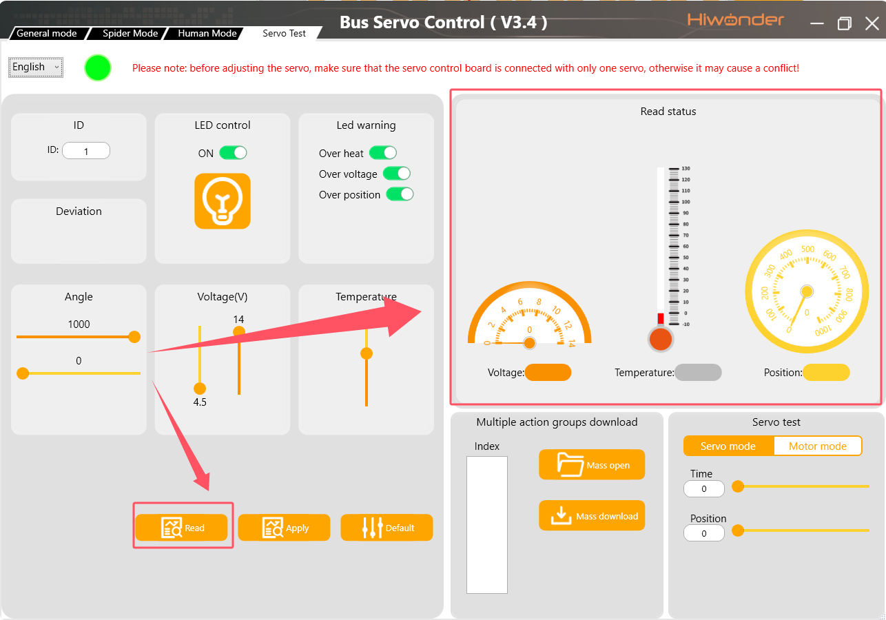
- Read the Servo ID: Click the Read button to retrieve the current servo data. The interface will display the current ID, temperature, voltage, and position of the servo as shown in the figure below, confirming a successful connection between the servo and the host computer.
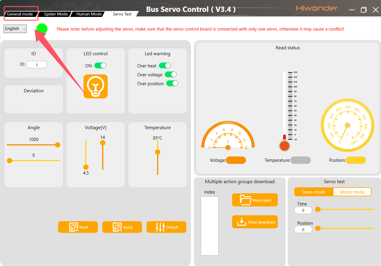
- Configure the Servo ID: Input the desired servo ID into the ID field, where this example uses an ID of 7, and click the Apply button. Wait a few seconds for the process to complete. If the configuration is successful, the page will display a completion message as shown in the figure below. If the configuration fails, verify that only one servo is connected and check the stability of the data cable connection.
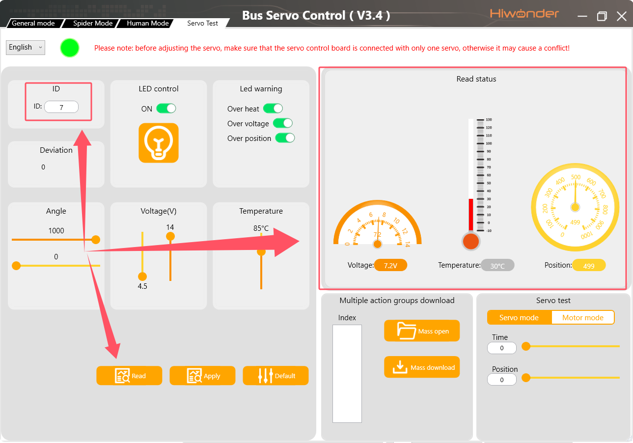
- Testing: Click the Read button after completing the servo ID configuration. The newly assigned servo ID will appear in the ID field of the software, and the current voltage, temperature, and position data of the servo will populate under the status field on the right, confirming a successful servo ID configuration as shown in the figure below.
Check whether the data cable functions properly if the PC software fails to connect to the serial bus servo controller.
This tutorial applies exclusively to Hiwonder serial bus servos and cannot be used for PWM servos.
Always select a power supply or battery within the specified driving voltage range of the serial bus servo.