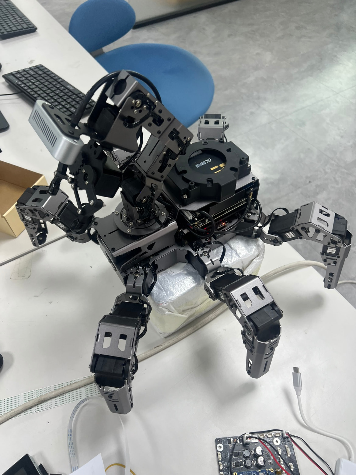
Using this template is recommended — you may also edit it freely, but you must fully describe your product and the problem (at least: product name, version, and problem description).
Product and Purchase
- Product model: Rospider
- SKU or kit name:
- Purchase channel: Hiwonder website
- Controller board:
Issue Description
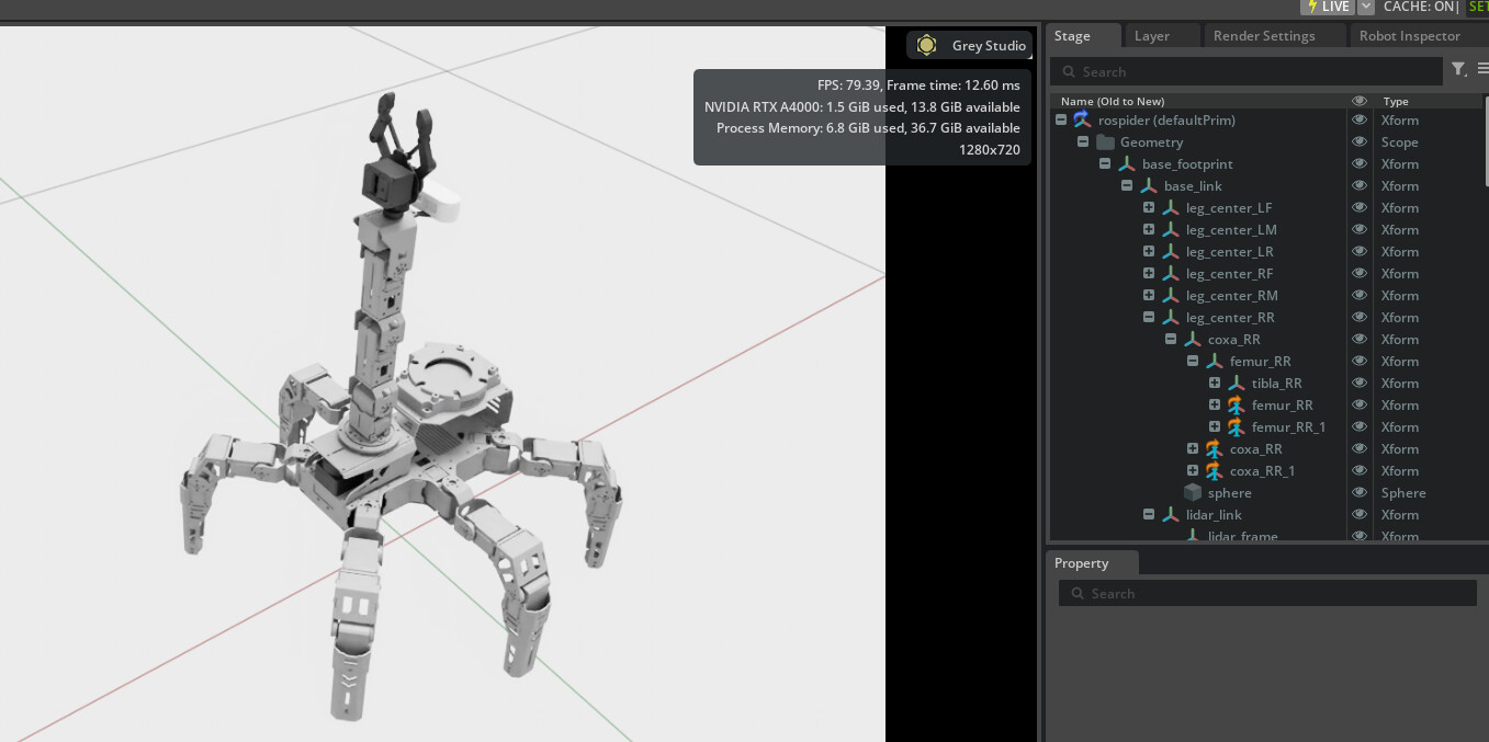
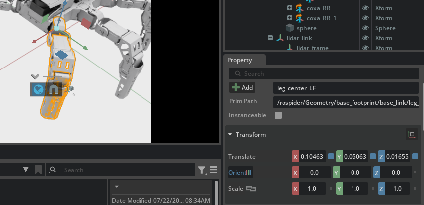
- What did you expect to happen? I’d like to learn Isaac Sim using RoSpider, but I don’t know the exact coordinate frames of each link and joint. Also, I’d like to add a custom part to RoSpider, but since I don’t know the existing coordinate frames, I can’t position the new part accurately. So I have a few questions:
- What 3D CAD program did you use to design this robot?
- How can we revise the coordinate frames if we want to make changes?
- If you used SolidWorks, did you use the sw2urdf tool to export the URDF?
Evidence
- Photos or short video:
What You Have Tried
- i’m studying Isaac sim with Rospider model.
-
And I’d like to move a link/joint to a different position, but I don’t know the coordinate frames. Furthermore, I want to revise the model and add another part to the robot, but as I mentioned, I don’t know the exact position of each link and joint’s coordinate frame. So what should I do in this case?
Thank you so much, as always. Hiwonder’s robot has been a huge help. Thank you.
Official support staff are being brought in to help with your questions. If you still need my help, reply here and @ me. @Hiwonder_Scarlett
Hi there,
Thank you for reaching out to Hiwonder Support. Please find the answers to your questions below:
1. Which 3D CAD software was used to design this robot?
We used SolidWorks to design ROSpider.
2. Was the sw2urdf tool used to export the URDF?
Yes, we used the sw2urdf tool to export the URDF model from SolidWorks.
3. How to check the exact positions of each link and joint coordinate frame?
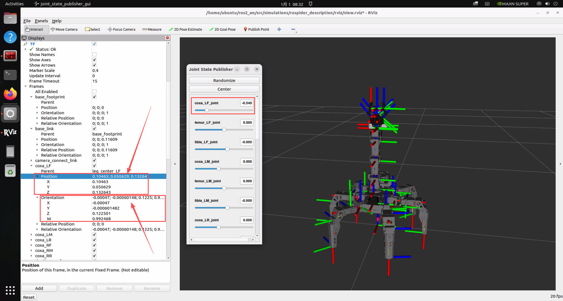
You can open RVIZ to inspect the coordinate frames by running the following command in the robot terminal:
ros2 launch rospider_description display.launch.py
In RVIZ:
-
Expand Frames under the TF panel to view all links. The Position value represents the coordinate origin relative to the Fixed Frame.
-
Dragging the sliders in the Joint State Publisher window lets you observe real-time changes in the Orientation (quaternions) on the left panel.
-
Relative Position and Relative Orientation display the origin coordinates and rotational state relative to the Parent link.
4. How to adjust or modify coordinate frames?
We currently do not have dedicated tutorials for Isaac Sim, but adjusting coordinate frames is primarily handled by editing the URDF/Xacro files.
Example: Run the following command in the terminal to edit the robotic arm’s Xacro file:
cd ros2_ws/src/simulations/rospider_description/urdf && gedit arm.urdf.xacro
Modify lines 42–44 to:
XML
<origin xyz="0.065006 0 0.102583" rpy="0 0 0"/>
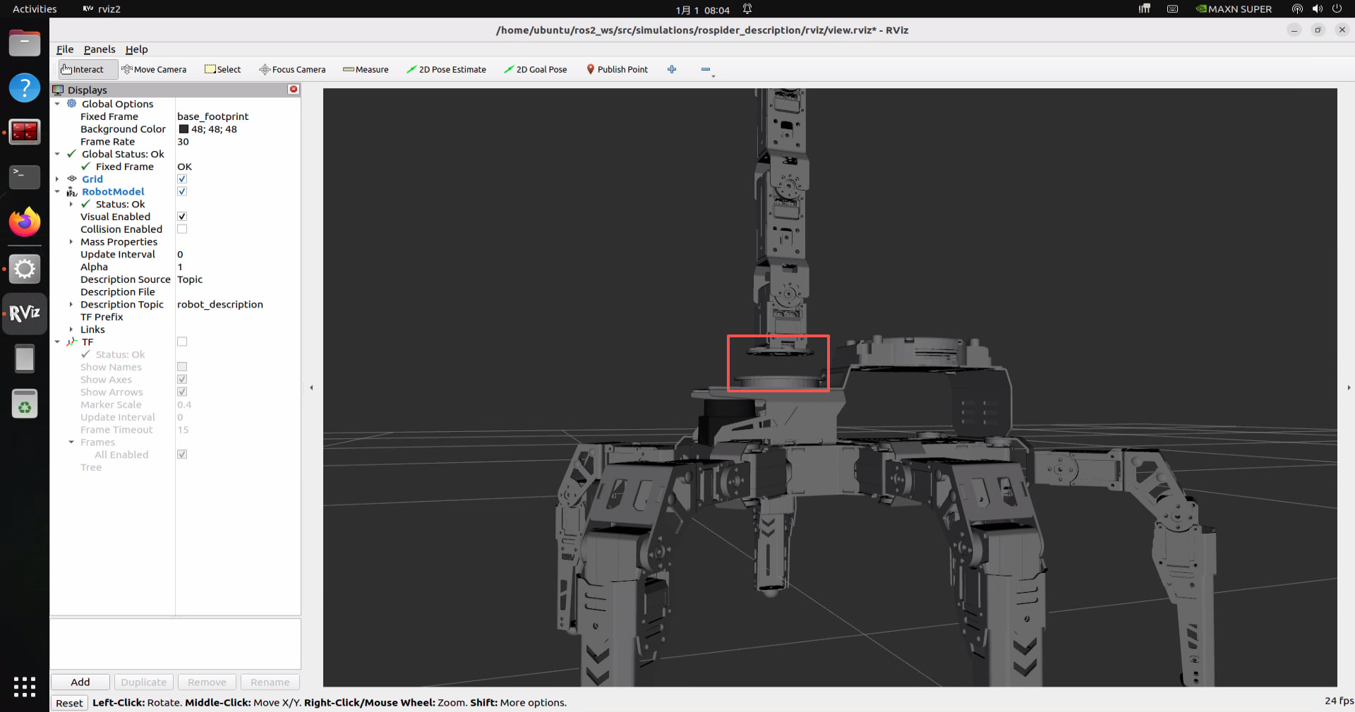
This shifts the entire robotic arm upward by 2 cm along the Z-axis of base_link, thereby updating its coordinate frame. This modification should take effect accordingly when imported into Isaac Sim. This is a demonstration of the result in the RViz tool after the modification.
Please feel free to reach out if you have further questions!
Oh! This answer also solved my problem really well. I’m also learning the same simulation feature, and this answer successfully helped me realize my idea. Awesome!